Welcome to the Raspberry Pi Traffic Symphony, where LEDs dance in a synchronized rhythm, emulating the bustling traffic lights of a city intersection. In this engaging and enlightening tutorial, we’ll embark on a journey of basic GPIO (General Purpose Input/Output) control on Raspberry Pi, transforming our mini-computer into a traffic light simulator. So, buckle up, and let’s navigate through the lanes of creativity and code!
Materials Needed:
- Raspberry Pi (any model with GPIO pins)
- MicroSD card with Raspbian OS installed
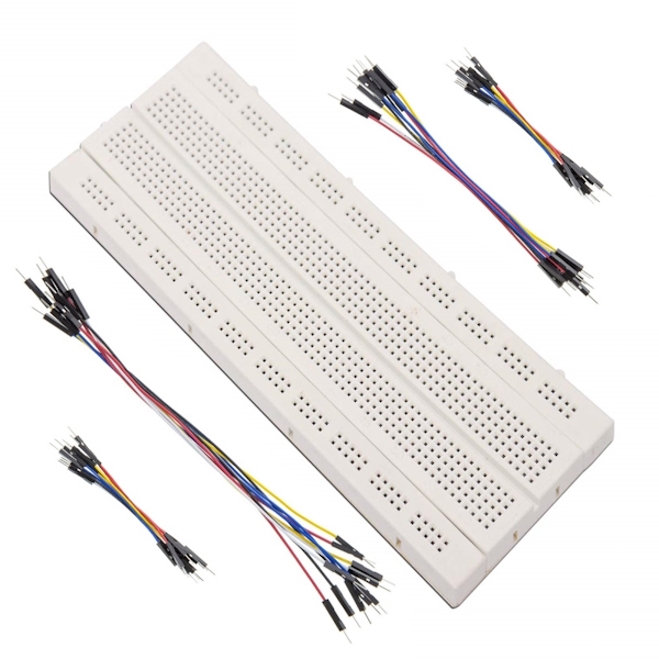
- Breadboard and jumper wires
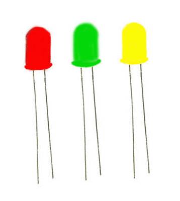
- Red, yellow, and green LEDs
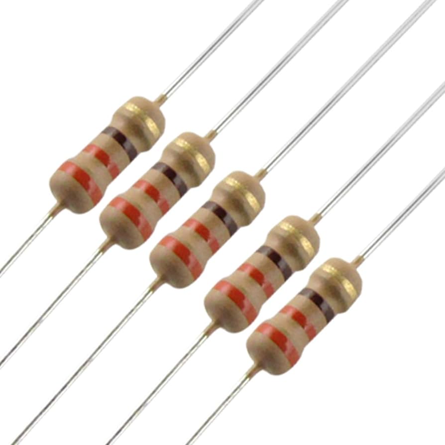
- Resistors (220-330 ohms)

Step 1: Set the Stage for the Traffic Symphony
Before we dive into the code, make sure your Raspberry Pi is set up and ready to roll. If you haven’t set up your Raspberry Pi yet, follow the instructions on the official Raspberry Pi website to install the Raspbian OS.
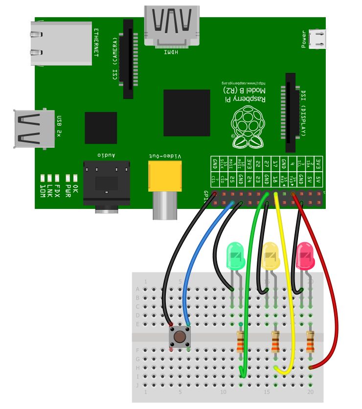
Step 2: Assemble the Traffic Light Ensemble
- Place the LEDs on the breadboard:
- Red LED in one row.
- Yellow LED in the next row.
- Green LED in the row after that.
- Connect each LED’s cathode (short leg) to the ground (GND) rail on the breadboard.
- Connect each LED’s anode (long leg) to a GPIO pin on the Raspberry Pi:
- Red LED to GPIO pin 17.
- Yellow LED to GPIO pin 27.
- Green LED to GPIO pin 22.
- Connect a resistor to the cathode of each LED, connecting the other end to the ground rail.
Step 3: Write the Traffic Symphony Script
Now, let’s compose the code for our Traffic Symphony. Open the Python IDE on your Raspberry Pi and create a new script. Enter the following code:
import RPi.GPIO as GPIO
import time

# Set up GPIO
GPIO.setmode(GPIO.BCM)
GPIO.setup(17, GPIO.OUT)  # Red
GPIO.setup(27, GPIO.OUT)  # Yellow
GPIO.setup(22, GPIO.OUT)  # Green

# Function to simulate traffic lights
def traffic_light_cycle():
    GPIO.output(17, GPIO.HIGH)  # Red
    time.sleep(2)

    GPIO.output(17, GPIO.LOW)   # Red off, Yellow on
    GPIO.output(27, GPIO.HIGH)
    time.sleep(1)

    GPIO.output(27, GPIO.LOW)   # Yellow off, Green on
    GPIO.output(22, GPIO.HIGH)
    time.sleep(2)

    GPIO.output(22, GPIO.LOW)   # Green off, Yellow on
    GPIO.output(27, GPIO.HIGH)
    time.sleep(1)

# Run the traffic light cycle indefinitely
try:
    while True:
        traffic_light_cycle()

except KeyboardInterrupt:
    # Clean up when the script is interrupted
    GPIO.cleanup()
Step 4: Run the Traffic Symphony
Save your script and run it in the terminal using the following command:
python your_script_name.pyObserve the LED symphony as it simulates the classic traffic light cycle: Red, Red+Yellow, Green, Yellow.
Step 5: Encore – Customize Your Symphony
Feel free to modify the code to create your unique traffic light sequence. Add features like pedestrian signals, countdowns, or even incorporate a button to trigger the light change.
Conclusion:
You’ve successfully orchestrated your Raspberry Pi Traffic Symphony, a playful and interactive project that goes beyond the basics of GPIO control. As you continue your Raspberry Pi journey, explore additional features, integrate sensors, and transform your traffic light simulator into a smart city traffic management system.
Stay tuned for more captivating Raspberry Pi projects and tutorials as you navigate the intersections of creativity and technology. Happy coding, Maestro! 🚦🎶