In this hands-on tutorial, we’re going to immerse ourselves in the world of traffic management using Arduino. Buckle up as we embark on a journey to create a Traffic Light Controller—a project that not only introduces you to Arduino programming but also mimics the crucial role of traffic lights in our urban landscapes. Let’s dive into the exciting realm of electronics and coding!
Materials Needed:
- Arduino board (e.g., Arduino Uno)
- Breadboard and jumper wires
- LEDs (Red, Yellow, Green)
- Resistors (220-330 ohms)
- Tactile switches (optional, for pedestrian crossing simulation)
- An external power source (if needed)
Overview:
Traffic light controllers play a pivotal role in regulating traffic flow and ensuring safety on the roads. In this project, we’ll simulate the behavior of a typical traffic light system with red, yellow, and green lights for vehicles, and optionally, a pedestrian crossing feature.
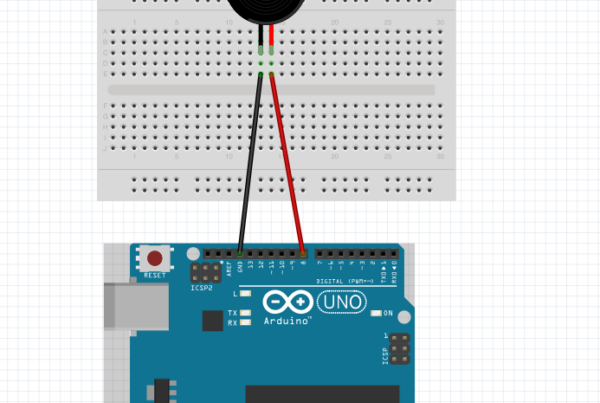
Step 1: Set Up Your Hardware:
- Connect LEDs: Place three LEDs on the breadboard—Red, Yellow, and Green. Connect the cathode (short leg) of each LED to a resistor and then to the ground (GND) rail on the breadboard. Connect the anode (long leg) of each LED to separate digital pins on the Arduino (e.g., 2, 3, and 4).
- Pedestrian Crossing (Optional): If you want to include a pedestrian crossing, add a tactile switch to the breadboard. Connect one leg of the switch to a digital pin on the Arduino (e.g., 5) and the other leg to the ground. Connect a resistor between the same digital pin and the power rail (5V).

Step 2: Write the Arduino Sketch (Code):
Now, let’s create the code for our Traffic Light Controller. Open the Arduino IDE and start a new sketch. Enter the following code:
const int redPin = 2;
const int yellowPin = 3;
const int greenPin = 4;
const int pedestrianPin = 5;

void setup() {
  pinMode(redPin, OUTPUT);
  pinMode(yellowPin, OUTPUT);
  pinMode(greenPin, OUTPUT);
  pinMode(pedestrianPin, INPUT);
}

void loop() {
  // Vehicle Traffic
  digitalWrite(redPin, HIGH);
  delay(5000);  // Red for 5 seconds

  digitalWrite(redPin, LOW);
  digitalWrite(yellowPin, HIGH);
  delay(2000);  // Yellow for 2 seconds

  digitalWrite(yellowPin, LOW);
  digitalWrite(greenPin, HIGH);
  delay(5000);  // Green for 5 seconds

  digitalWrite(greenPin, LOW);

  // Pedestrian Crossing (if button is pressed)
  if (digitalRead(pedestrianPin) == HIGH) {
    // Flashing green for pedestrian crossing
    for (int i = 0; i < 3; i++) {
      digitalWrite(greenPin, HIGH);
      delay(500);
      digitalWrite(greenPin, LOW);
      delay(500);
    }
  }
}
Step 3: Upload and Test:
- Connect your Arduino board to your computer.
- Select the correct board and port in the Arduino IDE.
- Click the upload button to upload the sketch to your Arduino.
Step 4: Watch the Traffic Light Symphony:
After uploading the sketch, your Arduino Traffic Light Controller is ready. Observe the LED lights on the breadboard mimicking the traffic light sequence. If you included the pedestrian crossing, press the tactile switch to initiate the pedestrian crossing phase.
Conclusion:
Congratulations! You’ve successfully crafted an Arduino Traffic Light Controller, a miniaturized version of the traffic management systems we encounter daily. This project serves as a foundation for expanding into more sophisticated traffic simulations or integrating sensors for real-world applications.
Stay tuned for more exciting Arduino projects and tutorials as you navigate the intersections of creativity and technology. Happy coding and safe travels! 🚦🔧